
🇵🇱 Polska wersja instrukcji jest poniżej.
🇬🇧 English version: scroll down or jump to the English manual ↓
🇵🇱 Instrukcja montażu i obsługi
Zanim zaczniesz
- Maksymalna masa użytkownika: 120 kg
- Maksymalna moc kolarza: 1200 W
- Wersja nogi: v1 (pierwsza seria)
Bezpieczeństwo:
- Nie przekraczaj podanych limitów masy i mocy.
- Przed jazdą upewnij się, że śruby wózka osi są dokręcone. Regularnie sprawdzaj śruby zgodnie z sekcją „Konserwacja”.
- Nie używaj nogi, jeśli którykolwiek element jest pęknięty lub uszkodzony.
- W rowerze z hamulcami tarczowymi zawsze zakładaj blokady klocków, gdy koło jest wyjęte.
Zawartość zestawu
Noga przychodzi w dwóch wstępnie zmontowanych częściach. Do złożenia zostaje tylko połączenie sekcji pionowej z blachą bazową.
- Blacha bazowa
Już zamontowane: adaptery pod piłki tenisowe, 3 piłki tenisowe - Sekcja pionowa (profil z ruchomym wózkiem osi)
Już zamontowane: adaptery osi wg wariantu (przy wariancie z kilkoma typami osi: adaptery 12×100 mm), blokada adapterów osi - Pozostałe adaptery osi (tylko w wariancie z kilkoma typami osi)
Luzem, w osobnym opakowaniu - Śruby M8 łączące blachę bazową z sekcją pionową
Jeśli zamówiłeś nogę z adapterami do kilku typów osi, na wózku są założone adaptery do najpopularniejszej osi 12×100 mm. Pozostałe adaptery są w zestawie osobno. Jeśli Twój rower ma inną oś, wymień adaptery zgodnie z sekcją „Wymiana adapterów osi”.
Potrzebne narzędzia
- Klucz imbusowy 6 mm (śruby blachy bazowej)
- Klucz imbusowy 5 mm (śruby wózka osi)
- Zalecany klucz dynamometryczny z zakresem 5-15 Nm
Montaż nogi
Elementy zmontowane fabrycznie są skręcone i ustawione. Nie rozkręcaj ich.
- Włóż dwie śruby M8 z zestawu w środkowy rząd otworów blachy bazowej.
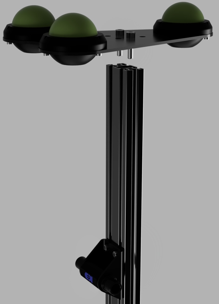
- Przyłóż blachę ze śrubami do końca sekcji pionowej i wkręć obie śruby kluczem imbusowym 6 mm. Zwróć uwagę na ustawienie blachy względem wózka z adapterami osi (jak na rysunku poniżej).
- Dokręć śruby momentem 15 Nm.
Wymiana adapterów osi
Adaptery dla zamówionego wariantu są zamontowane fabrycznie. W wariancie z kilkoma typami osi fabrycznie założone są adaptery 12×100 mm. Ta sekcja przyda się, jeśli Twój rower ma inną oś albo jeśli dokupisz adaptery pod inny standard osi.
Montaż:
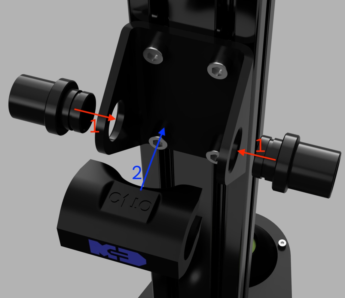
- Włóż odpowiednie adaptery z obu stron wózka, zgodnie ze strzałkami 1. Przytrzymaj je, żeby nie wypadły.
- Trzymając adaptery, wsuń blokadę od dołu, zgodnie ze strzałką 2.
Demontaż (w odwrotnej kolejności, przeciwnie do strzałek):
- Wysuń blokadę w dół, z wózka. Przytrzymaj adaptery, bo po wyjęciu blokady mogą wypaść.
- Wyjmij adaptery z obu stron wózka.
Montaż i demontaż mogą wymagać użycia sporej siły. Z każdym kolejnym razem będzie łatwiej, bo elementy blokady się dopasują.
Jeśli używasz osi z szybkozamykaczem (QR 9×100 mm), po założeniu adapterów przełóż szybkozamykacz ze swojego przedniego koła.
Zakładanie roweru i regulacja wysokości wózka osi
Regulacja służy do wypoziomowania roweru. Wystarczy ją zrobić raz dla danego trenażera. Bez obciążenia wysokość nie zależy od roweru.
- Załóż rower na trenażer. Zmierz odległość od podłogi do środka osi tylnego koła i zapisz wynik.
- Załóż nogę do widelca tak, jakbyś zakładał przednie koło. Dokręć oś zgodnie z zaleceniami producenta roweru.
- Postaw nogę na podłodze i dociśnij ją, żeby stabilnie się ułożyła i wszystkie trzy piłki równo przylegały do podłogi.
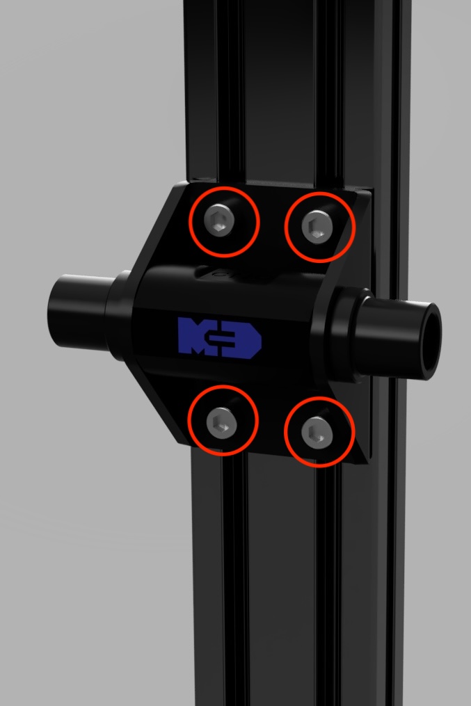
- Poluzuj kluczem imbusowym 5 mm cztery śruby wózka zaznaczone na rysunku poniżej. W pewnym momencie wózek zacznie przesuwać się po profilu z lekkim oporem.
- Ustaw wózek tak, żeby odległość od podłogi do środka osi przedniego koła była taka sama jak zmierzona wcześniej dla tylnego koła.
- Dokręć cztery śruby wózka momentem 7 Nm.
Dokładniejsza regulacja pod obciążeniem (opcjonalnie)
Piłki tenisowe uginają się pod obciążeniem, dlatego podczas jazdy wysokość przedniej osi może się nieco zmieniać. Ugięcie zależy od masy kolarza i od typu roweru, który wpływa na rozkład masy między przód a tył. Jeśli używasz w trenażerze nóg z piłkami tenisowymi, zmienia się też wysokość tylnej osi.
Dla większości kolarzy regulacja bez obciążenia, opisana powyżej, w zupełności wystarczy.
Jeśli chcesz uzyskać idealny wynik, poproś drugą osobę o pomoc:
- Usiądź na rowerze w typowej pozycji do jazdy.
- Druga osoba mierzy odległość od podłogi do środka osi tylnej i przedniej.
- Jeśli przednia oś jest niżej niż tylna, podnieś wózek o tę różnicę (zgodnie z krokami 4-6). Jeśli jest wyżej, obniż go.
⚠️ UWAGA: hamulce tarczowe
W rowerze z hamulcami tarczowymi zawsze zakładaj blokady klocków hamulcowych, gdy koło jest wyjęte, zarówno w przednim, jak i w tylnym hamulcu. Bez nich przypadkowe naciśnięcie dźwigni może zacisnąć klocki.
Współpraca z wahliwymi nogami trenażera
Noga została zaprojektowana jako uzupełnienie wahliwych nóg trenażera z piłkami tenisowymi.
Przechowywanie
Gdy noga nie jest używana, przechowuj ją w pozycji leżącej. Piłki tenisowe celowo dają jej trochę ruchu, więc sama łatwo się przewraca. Tak jak koło rowerowe nie stoi samo, tak i noga nie jest stabilna bez roweru.
Konserwacja
- Co 10 jazd: sprawdź dokręcenie śrub wózka osi (7 Nm), żeby wózek nie mógł się obniżyć.
- Co 2 miesiące: sprawdź dokręcenie śrub łączących blachę bazową z sekcją pionową (15 Nm).
- Mniej więcej raz w miesiącu: obróć piłki tenisowe w blasze bazowej, żeby zużywały się równomiernie i dłużej wytrzymały. Gdy zauważysz, że piłki są wyraźnie bardziej miękkie, wymień je na dowolne piłki tenisowe.
- Czyszczenie: wystarczy ręcznik papierowy i płyn do mycia szyb.
Rozwiązywanie problemów
Problem: Adaptery osi słabo się blokują
Przyczyna: Zużyta blokada adapterów. Blokada jest drukowana w 3D, więc przy częstym używaniu naturalnie się zużywa.
Co zrobić: Napisz do mnie, wyślę nową blokadę.
Kontakt i części zamienne
W razie problemów napisz na adres kontakt@mcdziakdesign.pl.
🇬🇧 Assembly and user manual
Before you start
- Maximum rider weight: 120 kg
- Maximum rider power output: 1200 W
- Leg version: v1 (first production batch)
Safety:
- Do not exceed the stated weight and power limits.
- Before riding, make sure the axle carriage bolts are tight. Check the bolts regularly as described in “Maintenance”.
- Do not use the leg if any part is cracked or damaged.
- On bikes with disc brakes, always fit pad spacers whenever the wheel is out.
What’s in the box
The leg arrives in two pre-assembled parts. The only thing left to assemble is the joint between the upright section and the base plate.
- Base plate
Already fitted: tennis ball holders, 3 tennis balls - Upright section (profile with sliding axle carriage)
Already fitted: axle adapters for your variant (multi-axle variant: 12×100 mm adapters), axle adapter lock - Other axle adapters (multi-axle variant only)
Loose, in a separate bag - M8 bolts joining the base plate to the upright section
If you ordered the leg with adapters for several axle types, the carriage comes fitted with adapters for the most common axle, 12×100 mm. The other adapters are packed separately. If your bike uses a different axle, swap the adapters as described in “Changing the axle adapters”.
Tools you need
- 6 mm hex key (base plate bolts)
- 5 mm hex key (axle carriage bolts)
- Recommended: torque wrench with a 5-15 Nm range
Assembling the leg
The factory-assembled parts are already bolted together and set up. Do not take them apart.
- Insert the two M8 bolts from the kit into the middle row of holes in the base plate.
- Place the plate with the bolts on the end of the upright section and screw in both bolts with a 6 mm hex key. Check how the plate is oriented relative to the carriage with the axle adapters (as shown in the drawing below).
- Tighten the bolts to 15 Nm.
Changing the axle adapters
The adapters for the variant you ordered are fitted at the factory. In the multi-axle variant, the 12×100 mm adapters are fitted. You will need this section if your bike uses a different axle, or if you buy adapters for another axle standard later.
Fitting:
- Insert the correct adapters into both sides of the carriage, following arrows 1. Hold them so they don’t fall out.
- While holding the adapters, slide the lock in from below, following arrow 2.
Removal (reverse order, against the arrows):
- Slide the lock down and out of the carriage. Hold the adapters, as they can fall out once the lock is removed.
- Pull the adapters out of both sides of the carriage.
Fitting and removing the adapters may take a fair amount of force. It gets easier each time as the lock parts bed in.
If you use a quick-release skewer (QR 9×100 mm), move the skewer over from your front wheel once the adapters are in place.
Mounting the bike and adjusting the carriage height
This adjustment levels your bike. You only need to do it once for a given trainer. Without a rider on the bike, the height does not depend on the bike.
- Mount the bike on the trainer. Measure the distance from the floor to the centre of the rear axle and write it down.
- Fit the leg into the fork just as you would fit the front wheel. Tighten the axle according to your bike manufacturer’s instructions.
- Stand the leg on the floor and press it down so it settles firmly and all three balls sit evenly on the floor.
- Using a 5 mm hex key, loosen the four carriage bolts marked in the drawing below. At some point the carriage will start to slide along the profile with slight resistance.
- Set the carriage so that the distance from the floor to the centre of the front axle matches the rear axle measurement you took earlier.
- Tighten the four carriage bolts to 7 Nm.
Fine-tuning under load (optional)
The tennis balls compress under load, so the front axle height may change slightly while you ride. How much they compress depends on the rider’s weight and on the type of bike, which affects how the weight is split between front and rear. If your trainer stands on feet with tennis balls, the rear axle height changes too.
For most riders, the unloaded adjustment described above is all you need.
If you want a perfect result, ask someone to help:
- Sit on the bike in your usual riding position.
- Your helper measures the distance from the floor to the centre of both the rear and the front axle.
- If the front axle is lower than the rear, raise the carriage by the difference (following steps 4-6). If it is higher, lower it.
⚠️ WARNING: disc brakes
On bikes with disc brakes, always fit brake pad spacers whenever the wheel is out, on both the front and the rear brake. Without them, an accidental pull of the lever can close the pads.
Using it with rocker-style trainer feet
The leg is designed to complement rocker-style trainer feet that use tennis balls.
Storage
When you are not using the leg, store it lying down. The tennis balls deliberately let it move a little, so on its own it tips over easily. Just as a bike wheel won’t stand up by itself, the leg is not stable without the bike.
Maintenance
- Every 10 rides: check that the axle carriage bolts are tight (7 Nm), so the carriage cannot slip down.
- Every 2 months: check that the bolts joining the base plate to the upright section are tight (15 Nm).
- About once a month: rotate the tennis balls in the base plate so they wear evenly and last longer. When you notice the balls have become noticeably softer, replace them with any standard tennis balls.
- Cleaning: a paper towel and glass cleaner are all you need.
Troubleshooting
Problem: Axle adapters don’t lock firmly
Cause: Worn adapter lock. The lock is 3D printed, so it naturally wears with frequent use.
What to do: Get in touch and I’ll send you a new lock.
Contact and spare parts
If you have any problems, email kontakt@mcdziakdesign.pl.